
UML State Diagram: Visualize Sequences of Object States
When developing a product or computer program, UML state diagrams can help to visualize the life cycle of each object in a clear and understandable way. Although this diagram only consists of a few elements, if used correctly it can contribute significantly to the final result. In the following sections, we explain why and in which cases it is worth making a UML state diagram and how to do it.
Index
- What is a UML state diagram?
- What is the UML state diagram for?
- State diagram: structure and components
- state
- Transition: how do you change state?
- External transition: change of state
- Internal transition: unaltered state
- Events: why is the state changed?
- Pseudo-states
- Complex diagrams
- Create a state diagram: example of a simple diagram
What is a UML state diagram?
A UML state diagram (also called a state diagram, state transition diagram, or state machine diagram) shows the states that a finite state machine goes through, that is, a behavior model consisting of actions and states. or transitions to other states. The diagram provides an initial and final state, as well as at least one intermediate state for each object. The state diagram allows, in this way, to represent the complete life cycle of any system, subsystem or components or classes thereof, such as a coffee machine, an electronic book reader or a technological component of a vehicle.
The state diagram is one of the 14 types of diagrams defined in the Unified Modeling Language (UML), or Unified Modeling Language, and in the Systems Model Language (SysML). It dates back to a concept proposed by David Harel in 1987 in his article Statecharts: A Visual Formalism for Complex Systems . Other types of UML diagrams are, for example, the use case diagram or the component diagram.
What is the UML state diagram for?
As we have already mentioned, the goal of state diagrams is to describe the behavior of a system with the utmost precision. Among other things, this graphical representation of the processes should answer the following questions:
- What happens when the object is in a specific state?
- What state must the object be in to change its behavior?
- What are the triggers?
- What properties must the object have in order to change state?
Therefore, UML state diagrams are used to optimize any development process where it is useful to visualize the object's states and conditions for the transition from one state to another. They are usually used, for example, in the design of embedded systems (in English, embedded systems ), where automated signals and background processes must be perfectly coordinated. In this case, the state diagram helps developers to visualize all the most important regulation and control functions in a single schematic.
The function of interrupting the water intake that almost all washing machines have can serve as an example to imagine a UML state diagram. In this context, this function would be represented as a separate system. In this case, the diagram would show in what state and under what conditions the function is activated.
Note
In various sectors of industry, such as transportation or healthcare technology, state diagrams are used to explain complex processes . They are also used in requirements engineering and in product and project management.
State diagram: structure and components
Although UML state diagrams are based on only a few elements, combining them intelligently allows us to easily represent complex state sequences. What are the main components and what is the basic structure of a state diagram?
state
States are the main component of a state diagram. Each actual state is always displayed in a rounded corner rectangle. For example, a door can have two status values:
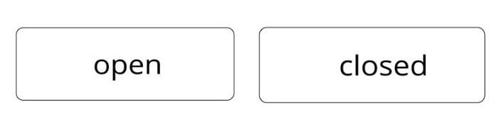
The two possible states of a door: it can be open or closed, but not both at the same time.
Likewise, the door status diagram would indicate that the following condition must always be met:
- The object is always in one of two states: the door is open or closed, but never open and closed at the same time.
In more complex state diagrams, the rectangle can be divided into up to three zones where behavioral specifications are shown (see transition).
Transition: how do you change state?
To move from one state to the next, an event that causes a transition must be fired. This state transition communicates the states with each other and is represented by an arrow. There may be conditions for such a transition to be triggered. Generally speaking, UML state diagrams represent internal and external transitions . A state diagram must always have some external transition, but it does not have to include internal transitions.
In the state diagram of an elevator, for example, you could specify the following condition for the action? Close elevator door ?: that the elevator has been open at least five seconds before the state changes from? Open? to? closed ?.
External transition: change of state
The transition in the following example is considered external and results in the object changing state ( entry / exit ).
Example : after a radio alarm goes off, the status changes from? Alarm on? to? alarm off ?.

When the alarm is activated, the object changes state: if the alarm was activated a moment ago, it is now deactivated.
Internal transition: unaltered state
An internal transition does not trigger a state change, but an activity .
Example : some accounting systems resend invoices without automatically paying the customer (external transition). If what they send is a reminder that the invoice is pending payment, this represents an internal transition: that is, although there is an activity (? Send the reminder?), The invoice remains in the same state (? Not paid?) until new notice.
Events: why is the state changed?
Through events it is possible to describe in more detail the conditions under which one state is left to go to the next. In the case of the transition from the initial state to the first real state, it is not necessary, but more information can be added optionally. If no event is indicated, it means that the event occurs automatically as soon as all activities in the previous states have been completed.
If the trigger is not indicated, it means that this event is always taking place . Events can be represented as a specification of behavior within the state or within the transition to another state (see transition).
A triggering event must meet the following three conditions :
-
entry : the event is fired automatically when a state is triggered, that is, on all incoming transitions.
-
exit : the event is fired when a state is exited, that is, on all outgoing transitions.
-
do : the event is fired over and over again if the state is not changed.
These indications can be noted within the state itself to simplify the representation of the behavior under which the state changes. There are two options for displaying these triggers graphically. One of them is to indicate them within the corresponding status box, as the following example of a state diagram illustrates:
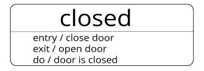
The state of a door is "closed". To enter this state, the event? Close the door? Must first take place. (entry). When the state is exited, the event? Open the door? (exit). During the state, is the door (permanently) closed? (do).
Events can also be indicated by a transition arrow:
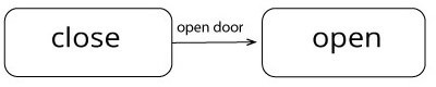
In simple state diagrams, events are noted on the transition arrow.
Pseudo-states
In UML state diagrams, if some control element influences the operation of a state machine, but has no value assigned to it, it is called a pseudo-state. In UML 2, the current version of the Unified Modeling Language, the following ten pseudo-states are defined:
-
Initial state (in English, initial ): without incoming transition and with an outgoing transition that reveals what the state is at the beginning of the sequence.
-
Final state (in English, final ): no outgoing transition; end of behavior sequence.
-
Fork ( fork ): division into several parallel states.
-
Synchronization (in English, join ): synchronization of several parallel states.
-
Union (in English, junction ): node of union of several transitions in series.
-
Choice (English, choice ): i node from which various transitions can be initiated on the basis of a previous decision.
-
Entry point (in English entry point ): synthesis of similar transitions entering a compound state.
-
Starting (English, exit point ): synthesis of similar transitions that originate in a compound state.
-
History surface (English, shallow history ) of the last active storage substate of a compound state.
-
Deep history (in English, deep history ) storing the last active substate all levels of a compound state.
Complex diagrams
Depending on the complexity of the process, it is possible to include substates in the schematic that show a detailed image of each state of the object and its possible behavior. This more complex version of the UML state diagrams is usually the most common, especially in the technical field.
-
Composite state : this structure allows defining a state in depth .
Example : a door can be in two states:? Open? or? closed ?. The substates of the state? Closed? could they be? blocked? and? unlocked ?.
-
Submachine State : The state includes a subordinate state diagram . A substate that consists of several substates is called a complex state. The various substates can both run independently of each other and be related to each other.
Example : the wake-up function of a smartphone is one of the many functions that can be related to other states. If different alarms are programmed for different times and days of the week, the entire process will consist of substates that run independently.
Create a state diagram: example of a simple diagram
State diagrams can be applied to objects of all kinds. In the following example, we show you how to include each item in the diagram of an invoice. These are the most important elements of a UML state diagram:
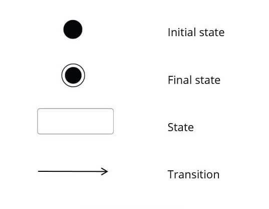
The most important elements of a UML state diagram.
If we combine the elements for our example, a simple diagram might look like this:
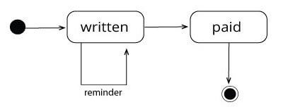
In this example, the UML state diagram has an internal transition.
At the starting point, the invoice is in the pseudo-state? written ? ( written ). At best, the transition to? Paid? ( paid ). This transition could be described in more detail by indicating the event "send". 
Once it has been paid, the invoice is in the status? Paid? . Before reaching this state, it may be necessary to send a? Reminder? ( reminder ). In this case, as the invoice does not change state, even if an activity occurs, it is an internal transition . If the bill is not paid, up to three reminders will be sent.